Introduction
Last week an EV motor design team from Chennai sent us an enquiry. They have designed a synchronous reluctance (SynRM) traction motor that they want to supply to Europe. The drawing asked for a 230 mm stator in 0.15 mm Backlack electrical steel with a core-loss limit of 2.3 W/kg at 1.5 T and 50 Hz, plus separate loss limits at 400 Hz and 700 Hz.
Ten years ago an Indian motor maker would not have written that specification. Today a growing number of them do. This article explains, in plain language, why the lamination has become the centre of the EV motor efficiency story, how Backlack bonding works, where copper and iron losses come from, and what a press shop like SNV can do to help a motor designer reach the number on the drawing.
Body: where the losses in an EV motor come from
An electric motor converts electrical power into mechanical power. Whatever does not become torque becomes heat. The heat has four main sources:
- Copper loss (I²R). Current through the winding resistance. Large at low speed and high torque, when the motor is pulling a heavy load up a hill.
- Iron loss (core loss). Loss inside the steel laminations as the magnetic field changes direction hundreds of times a second. Large at high speed, when the electrical frequency is high.
- Magnet loss. Eddy currents inside the permanent magnets, mainly at high frequency.
- Mechanical loss. Bearings, windage, and the oil or air that cools the motor.
Iron loss itself has two parts. Hysteresis loss is the energy spent each cycle to re-orient the magnetic domains in the steel; it rises with frequency. Eddy-current loss is the energy wasted by small circulating currents that the changing field induces inside each sheet; it rises with the square of frequency and the square of sheet thickness.
That second point is the whole reason laminations exist. A solid steel core would be one big eddy-current loop. Slicing it into insulated sheets of 0.50 mm, 0.35 mm, 0.20 mm or 0.15 mm cuts the loop size, and the loss drops with the square of the thickness.
Why EV motors are different from the motors we grew up with
A mixer-grinder motor runs at 50 Hz. A ceiling-fan BLDC motor might run at 30–50 Hz electrical. An EV traction motor at 15,000 rpm with 8 poles runs at 1,000 Hz. At that frequency, a lamination that was fine for a pump becomes a heater. This is why traction motors use thin, high-silicon, low-loss steel, and why how the sheets are joined has moved from a production detail to a design decision.
The problem: the stack is only as good as its weakest joint
A stator core is 150 to 400 thin sheets. They have to be held together. For decades there were three ways, and each one damages the thing the designer paid for:
| Joining method | How it holds the stack | What it does to the motor |
|---|---|---|
| Interlocking (clinch tabs) | A tab is pressed through several sheets in the die | Steel-to-steel contact at every tab, insulation cut, local stress. Worst for core loss. Not practical below about 0.30 mm sheet. |
| Welding (laser or TIG) | A bead along the outside diameter bridges every sheet | Every sheet is shorted at the weld line and the heat-affected zone loses its grain structure. Measured: about 10% higher stator core loss, with the excess-loss component roughly doubling (Aalto University, 37 kW motor). |
| Loose stack in a housing | Pressed or shrunk into the housing | No electrical damage, but compressive stress raises hysteresis loss and the stack can move, hum and fret. |
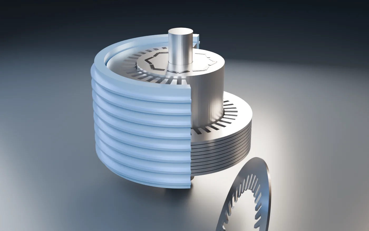
| Backlack bonding | A 3–6 µm epoxy varnish applied at the steel mill is cured under heat and pressure after stamping | Every sheet glued over 100% of its face. No metallic contact, no deformation, full insulation kept. Published results: 15% to 44% lower core loss than interlocked stacks of the same steel. Noise reduced up to five times. |
So the designer who specifies 0.15 mm steel and Backlack is not being fussy. A 0.15 mm sheet cannot be interlocked, welding would throw away a third of the gain, and bonding is the only method that keeps the loss the steel mill promised.
Root cause: three places where efficiency leaks out of a lamination
When a finished motor misses its efficiency target, the fault is rarely in the steel certificate. In our experience it is in one of three places:
- The cut edge. Punching work-hardens the steel for 0.3–1 mm beside every cut. On a wide yoke this is nothing; on a 2 mm wide EV stator tooth it can be a quarter of the tooth. Chalmers University modelled this punching effect at 10% to 35% extra hysteresis loss depending on edge quality. Sharp punches, correct clearance (4–6% of sheet thickness) and low burr are not cosmetics; they are efficiency.
- The joint. Weld beads and interlock tabs, as above. Each one is a short circuit between sheets, and a short circuit is an eddy-current path the designer never drew.
- The stack. Uneven pressure, burrs that hold sheets apart, and out-of-parallel stacking all lower the stacking factor (the share of the stack that is actually iron). Every percent of stacking factor lost is a percent of flux the motor has to find somewhere else.
Solutions: what a press shop can actually do
This is the part we care about most, because it is where SNV earns its place in a motor programme. A press shop that treats laminations as commodity sheet metal fixes none of the three leaks above. A press shop that understands the motor can fix all three.
1. Backlack bonding, done properly
"Backlack" is German for baking varnish. The steel mill applies a half-cured (B-stage) epoxy to both faces of the coil. We stamp it like any coated coil, collect the loose sheets to the exact count, clamp the stack at 1–3 MPa and cure it, typically 200 °C for two hours in an oven, or 240 °C for two minutes under induction in a bonding press. The two varnish films flow together and cross-link into one layer. The result is a stack that is quieter, stiffer, media-tight for oil cooling, and, most important, electrically clean.
Bonding-varnish grades are now available from Baosteel (the B20AV1000 and B25AV1000 family, where "AV" marks the self-bonding coating), from JFE and Nippon Steel in Japan, and from voestalpine and Waelzholz in Europe. We work with the customer's preferred mill and handle the storage and curing discipline the varnish demands: dry storage, under 40 °C, used within six months, full stack at temperature for the full hold time.
2. The right sheet thickness for stator and rotor, separately
The stator sees the full electrical frequency. The rotor of a PMSM or SynRM sees mainly slip harmonics and slotting ripple, at a much lower effective frequency, but it sees high centrifugal stress. So the thin, expensive, lower-strength 0.15–0.20 mm grade belongs in the stator; the rotor can often use 0.25–0.35 mm in a stronger, cheaper grade with no measurable efficiency penalty. On the Chennai SynRM enquiry this single decision reduced the material cost of the rotor by roughly a third. A commodity stamper would have quoted the same steel for both because the drawing said so.
3. Segmented stators
A 230 mm full-ring stator lamination wastes the steel inside the bore and in the corners of the strip. Cutting the stator as 6, 9 or 12 segments and bonding each segment separately raises sheet yield from around 45% to over 70%, allows a wider range of coil widths, and lets the winding be done on the open segment with higher copper fill, which cuts copper loss too. Segments need a bonded stack because welding a segment edge would destroy the tooth. We offer segmented laminations as a standard option for stators above 200 mm.
4. Lancing, welding and bonding: choosing with the numbers
Not every programme can carry the Backlack premium, which is roughly 15–30% on the steel price plus the curing cost. For those we offer stitched (lanced) stacks and laser-welded stacks, and we tell the designer what each one costs in loss. A fair rule from the published work: interlocking adds the most loss and is not available on thin sheet; welding adds around 8–10% core loss; bonding adds the least and recovers 15–44% of what the others throw away. For a pump motor the difference is a rounding error. For a traction motor it decides the range.
5. Edge quality as a controlled parameter
Our Yadon J76-220 press is a double-plunger design: the slide is driven at two points, so the tool stays parallel to the bolster within 50 µm across a 1900 × 950 mm slide. On a 230 mm die that means the clearance is the same at every tooth, the burr is the same at every tooth, and the work-hardened edge is as narrow as the punch grind allows. We measure burr on every lot and hold it at or below 0.02 mm. On thin high-silicon sheet this is the difference between a core that meets its W/kg and one that does not.
What 1% of efficiency is worth
Motor designers now fight for tenths of a percent, and here is why it is not vanity. Take a passenger EV that uses 15 kWh per 100 km and drives 15,000 km a year. Its traction motor handles roughly 2,250 kWh a year. One point of motor efficiency is about 22 kWh a year on the road, and because the same loss appears again during regenerative braking and as heat the cooling system must remove, the real saving is nearer 40–60 kWh a year per car.
For an electric bus using 1.2 kWh per km over 60,000 km a year, one point is around 700–1,000 kWh a year. Over a 12-year life that is 8–12 MWh per bus, before you count the smaller battery, lighter cooling and lower warranty risk that come with a cooler motor. A fleet operator with 500 buses buys the motor with the better lamination every time, and the tender documents now ask for the loss curve.
How SNV works with a motor designer
- We read the motor, not only the drawing. Speed, poles, frequency, cooling, duty cycle. From that we suggest grade and thickness for stator and rotor separately.
- We put three options on one page. Welded, stitched, bonded; full ring or segmented; with the loss trade-off and the cost of each, so the designer can decide with numbers.
- We prototype in small numbers. Single stacks and pilot lots, with burr, stacking factor, stack height and perpendicularity reports, and core-loss testing when the programme needs it.
- We carry the process discipline. Dry coil storage, varnish-compatible stamping lubricant, thermocouple-verified cure, peel and lap-shear coupons from every coil lot.
- We transfer to production on the same press. The 220-ton line that made the prototype makes the production part, so what the lab validated is what the line delivers.
We do this because we are not satisfied being a machine shop that happens to own a press. We have put our working lives into laminations, and the measure of our work is how close the finished motor gets to the efficiency the designer imagined.
Summary
- At EV speeds iron loss can be more than half of all motor loss; the lamination is the lever.
- Eddy-current loss falls with the square of sheet thickness: 0.35 → 0.20 mm cuts it by about two-thirds.
- Interlocking and welding short the sheets; Backlack bonding keeps the insulation and recovers 15–44% of core loss.
- Stator and rotor should be specified separately; segments raise yield on large stators.
- Edge quality, parallelism and burr are efficiency parameters, not cosmetics.
- One point of efficiency is worth 8–12 MWh over the life of an electric bus.
References
- Eurogroup Laminations / Charged EVs: glued vs interlocked EV stators, 15–44% core-loss reduction, noise up to 5× lower.
- Aalto University (Sundaria et al.): effect of laser welding on a 37 kW stator, about 10% higher stator core loss.
- Chalmers University: punching effect raises PMSM hysteresis loss by 10–35%.
- voestalpine isovac Backlack Processing Guidelines; Kansai Helios Electrical Steel Summit 2026; Tomková et al., Crystals 2026.
- KTH Royal Institute of Technology: iron loss share in induction and high-speed PM motors.