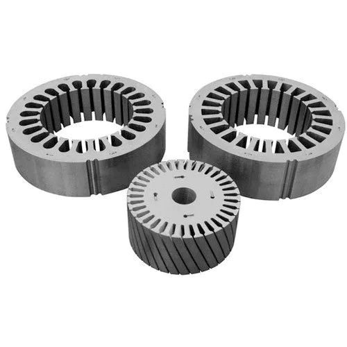
Quick answer: A motor lamination is a thin sheet of electrical steel (usually 0.20 to 0.65 mm thick) cut into the shape of a stator or rotor. Hundreds of these sheets are stacked and joined to form the motor core. Laminations are used instead of a solid block of steel because the thin, insulated sheets stop eddy currents, which cuts energy loss, keeps the motor cool and raises efficiency.
Introduction
Open any electric motor – a ceiling fan, a mixer grinder, a water pump, an EV traction motor – and you will find the same thing inside: a stack of thin steel sheets with slots cut into them. These sheets are called motor laminations (also called electrical steel laminations, stator laminations, rotor laminations, or motor stampings).
At SNV Stamping Solutions we make these laminations every day on a 220-ton high-speed press in Bengaluru. Customers, students and buyers often ask us the same basic questions: What exactly is a lamination? Why not use a solid piece of iron? Which material and thickness should I choose? This article answers those questions in plain language, from the shop floor.
Body: what a motor lamination is and how the idea came about
Definition
A motor lamination is a single, flat sheet of soft magnetic steel, punched or cut into the exact profile of the stator (the fixed outer part of the motor) or the rotor (the rotating inner part). Each sheet carries a very thin insulation coating. When many sheets are stacked on top of each other, aligned, and held together by welding, interlocking (cleating), riveting or bonding, the stack becomes the motor core. The copper winding sits in the stator slots, and the magnetic field produced by that winding passes through the steel of the laminations.
So a lamination is the "iron" of the motor. The copper carries the current; the lamination carries the magnetic flux.
A short history
The first motors of the 1880s used solid iron cores. Engineers quickly noticed that the cores became hot and wasted power. The reason was discovered to be circulating currents inside the iron, named eddy currents after the swirling eddies in a river. By the 1890s manufacturers had started building cores from stacked thin sheets with varnish or paper between them. In the early 1900s silicon was added to the steel (Hadfield, 1900) to raise its electrical resistance, and modern electrical steel was born. More than a century later, the principle is unchanged: thinner, insulated, silicon-alloyed sheets mean lower loss.
The purpose of laminations – why not a solid core?
When the magnetic field inside the motor changes direction (which happens 50 times a second in a 50 Hz induction motor, and hundreds of times a second in a high-speed BLDC or EV motor), it induces voltage inside the steel itself, just as it does in the copper winding. In a solid block of steel this voltage drives large eddy currents in big loops. Those currents do no useful work; they only heat the core.
Laminations solve this in two ways:
- They cut the loops short. The insulation between sheets stops current from flowing from one sheet to the next. Each eddy current is confined to a sheet that is a fraction of a millimetre thick, so the loop is tiny and the loss is tiny. Eddy-current loss falls roughly with the square of sheet thickness – halving the thickness cuts this loss to about one quarter.
- They give the flux a clear path. The slot shape, tooth width and back-iron depth are all cut into the sheet, so the magnetic circuit is defined precisely in every layer.
The result is a core that runs cooler, wastes less electricity, and lets the motor reach IE3, IE4 or EV-level efficiency.
The two losses a lamination controls
Engineers call the total loss inside the core the iron loss or core loss, measured in watts per kilogram (W/kg). It has two parts:
- Eddy-current loss – reduced by thinner sheets and higher silicon content.
- Hysteresis loss – the energy spent re-magnetising the steel each cycle. Reduced by better steel grade, larger grain size, and by avoiding damage to the sheet edges during stamping.
A good lamination supplier works on both: choosing the right grade and thickness, and stamping it with sharp tools so the edges are not work-hardened.
Problem: what goes wrong when laminations are chosen or made badly
Motor makers come to us with a familiar list of complaints:
- The motor runs hotter than the design calculation predicted.
- Efficiency measured on the test bench is 1 to 3 percentage points below target, so IE3 or IE4 certification fails.
- Noise and vibration are higher than the prototype.
- Stacks are not square, so the rotor rubs the stator or the air gap is uneven.
- The core "sings" or loosens after a few months in the field.
Every one of these is a lamination problem before it is a motor problem.
Root cause: five things that quietly raise core loss
- Wrong thickness for the operating frequency. A 0.50 mm sheet is fine for a 50 Hz pump motor. In a 400 to 1,000 Hz EV or high-speed BLDC motor the eddy-current loss in the same sheet is many times higher.
- Wrong grade. Using a low-grade or non-oriented steel with high W/kg loss to save a few rupees per kilogram, then losing far more in electricity bills over the life of the motor.
- Burr and edge damage from a worn die. A burr above 0.03 to 0.05 mm can bridge the insulation between sheets and short them together. Shorted sheets behave like a thick sheet – the eddy currents come back. Punching also hardens a narrow band at the cut edge and raises hysteresis loss there.
- Too much welding or interlocking. Every weld bead and every interlock tab is an electrical bridge between sheets. Necessary for holding the stack, but it must be kept to the minimum.
- Low stacking factor. If the sheets are wavy, dirty, or the burr holds them apart, the stack contains air instead of steel. A stacking factor of 95% instead of 98% means 3% less iron carrying the flux, so the steel saturates earlier and runs hotter.
Solutions: how to choose and specify motor laminations
1. Types of motor laminations
Laminations are usually classified three ways.
By position in the motor
- Stator laminations – the outer ring with slots facing inward (or outward in an outer-rotor motor). The winding sits in these slots.
- Rotor laminations – the inner disc. In an induction motor it has slots for the aluminium or copper cage; in a permanent-magnet motor it has pockets for the magnets; in a SynRM it has flux barriers.
- Armature laminations – the rotating slotted core of a universal or PMDC motor (mixer grinders, power tools, starter motors).
- Field or pole laminations – the stator of a universal or shaded-pole motor.
By motor type
- Induction motor laminations – pumps, fans, compressors, industrial drives. Usually 0.50 or 0.35 mm.
- BLDC and PMSM laminations – ceiling fans, air-conditioner fans and compressors, e-bikes, drones, appliances. Usually 0.35 mm; thinner for high speed.
- EV traction motor laminations – 0.20 to 0.30 mm, often bonded (Backlack) rather than welded.
- SynRM and reluctance motor laminations – complex rotor cut-outs, where punching accuracy decides torque ripple.
- Universal and PMDC motor laminations – armatures and fields for home appliances and automotive sub-systems.
By how they are made
- Progressive-die stamped – the standard for volume production. Fast, accurate, lowest cost per piece above a few thousand sets.
- Laser-cut – no tooling cost, good for prototypes and very small lots, but the heat-affected edge raises core loss and the cost per piece is high.
- Wire-EDM or chemically etched – special cases, very thin or exotic alloys.
- Segmented – large stators made as several arc segments to improve material yield, then assembled into a ring.
2. Materials
| Material | Typical grades | Where it is used | Notes |
|---|---|---|---|
| Non-oriented silicon steel (CRNO / CRNGO / NOES) | M400-50A, M350-50A, M300-35A, M250-35A, 35WW300, 30WW230, 20WW1200 | Almost all rotating motors | Magnetic properties are the same in every direction, which rotating machines need. The grade number is the maximum core loss in W/kg × 100 at 1.5 T, 50 Hz; the last number is thickness in 0.01 mm. |
| Grain-oriented silicon steel (CRGO) | M4, M5, 23ZH, 27ZH | Transformers, some large generator segments | Very low loss in the rolling direction only; not suitable for most motors. |
| Cold-rolled low-carbon steel (CRCA) | CR2, CR3, DC04 | Low-cost universal motors, shaded-pole motors, some mixer-grinder fields | Cheap, but 2 to 3 times the core loss of CRNO. Fine for intermittent-duty appliances; not for continuous-duty or efficiency-rated motors. |
| Thin-gauge and high-frequency grades | 0.20, 0.25, 0.27, 0.30 mm; Backlack-coated (B20AV1000, B25AV1000) | EV traction, high-speed spindles, aerospace | Self-bonding varnish allows gluing the stack with no welds or interlocks. |
| Cobalt-iron and nickel-iron alloys | Vacoflux, Permendur, Mu-metal | Aerospace, defence, instruments | Highest saturation or highest permeability; very expensive; special stamping and heat treatment. |
| Amorphous and nano-crystalline ribbon | Metglas 2605 | Research motors, some high-frequency machines | Extremely low loss but very thin (0.025 mm) and brittle; difficult to stamp and stack. |
In India the common CRNO grades are supplied by POSCO Maharashtra, JSW, Thyssenkrupp (Nashik) and imports from Baosteel, JFE and Nippon Steel. For most appliance and industrial motors, M400-50A to M250-35A covers the range; for EV and high-efficiency work, 0.20 to 0.30 mm grades are specified.
3. Sheet thickness – how to choose
Thickness is the single most important lamination decision. The rule is simple: the higher the electrical frequency and the higher the efficiency target, the thinner the sheet.
| Thickness | Typical application | Why |
|---|---|---|
| 0.65 mm | Older or low-cost 50 Hz motors, some welding transformers | Cheapest to stamp and stack; highest loss. Falling out of use. |
| 0.50 mm | Standard 50 Hz induction motors, pumps, IE2/IE3 motors | Good balance of cost and loss at mains frequency. |
| 0.35 mm | IE3/IE4 induction motors, BLDC fans and compressors, appliances, generators | About half the eddy-current loss of 0.50 mm; the most common choice for new designs. |
| 0.25 – 0.30 mm | High-speed BLDC, e-bike and two-wheeler motors, EV auxiliaries | Needed when electrical frequency reaches 300 to 600 Hz. |
| 0.20 mm and below | EV traction motors, aerospace, high-speed spindles | For 600 to 1,000+ Hz. Usually bonded; needs a precise press with low parallelism error. |
Two practical notes. First, thinner sheets mean more sheets per stack, so stamping time and handling cost rise – a 0.20 mm stack has 2.5 times as many strokes as a 0.50 mm stack of the same height. Second, thin sheets demand a press with tight slide parallelism (SNV's 220-ton line holds about 50 µm) and sharp tooling; otherwise burr becomes a bigger fraction of the sheet thickness.
4. Insulation coating
Every electrical-steel sheet comes with a factory coating, classified by the ASTM/EN "C" codes: C3 (organic), C5 (inorganic with organic filler) and C6 (thick inorganic) are the common ones for motors. The coating is 1 to 3 µm thick and must survive stamping, stacking and any stress-relief annealing. Backlack is a special additional varnish that softens with heat and glues the sheets together.
5. Quality parameters to put on the drawing
- Material grade and thickness (for example M350-50A, 0.50 mm) – with the core-loss limit in W/kg.
- Burr height – typically ≤ 0.03 mm; SNV holds ≤ 0.02 mm.
- Slot and bore dimensions – usually ±0.03 to ±0.05 mm.
- Stacking factor – 97 to 98% for a good stack.
- Stack height and squareness – stack height ±0.3 mm, perpendicularity within 0.1 mm per 100 mm.
- Joining method – weld, interlock, rivet or bond, and how many points.
- Skew angle if required for low cogging and noise.
6. How SNV makes motor laminations
Our line in Bengaluru runs a Yadon J76-220 double-plunger high-speed press with a Yaskawa servo feeder, handling strip from 0.20 to 1.0 mm thick and up to 400 mm wide. Progressive dies stamp the stator and rotor in one pass, and in-die stacking with skew is available. Every lot is checked for burr, dimensions and stacking factor before dispatch, and we keep our dies in-house for maintenance so the edge quality stays constant from the first lot to the hundred-thousandth. We supply laminations for induction, BLDC, PMSM, PMDC, universal, SynRM and EV traction motors, and support customers from single prototypes to millions of sets a year.
Summary
- A motor lamination is a thin, insulated sheet of electrical steel shaped as a stator, rotor or armature; stacked sheets form the motor core.
- Laminations exist to stop eddy currents, which cuts heat and loss and raises efficiency.
- Types are classified by position (stator, rotor, armature, field), by motor (induction, BLDC, PMSM, EV, SynRM, universal) and by process (stamped, laser-cut, segmented).
- Non-oriented silicon steel (CRNO) is the standard material; CRCA is for low-cost appliance motors; thin Backlack grades for EV; cobalt-iron for aerospace.
- Thickness runs from 0.65 mm (old 50 Hz motors) down to 0.20 mm (EV traction). Higher frequency and higher efficiency need thinner sheets.
- Burr, stacking factor, joining method and edge damage decide whether the steel you paid for performs as rated.
Frequently asked questions
What is a motor lamination in simple words?
It is one thin sheet of special steel, cut to the shape of the motor's stator or rotor. Many of these sheets stacked together make the iron core of the motor.
Why are motor cores laminated instead of solid?
A solid core lets large eddy currents circulate and wastes power as heat. Thin insulated sheets break those currents into tiny loops, so the core runs cool and the motor is more efficient.
What material are motor laminations made of?
Mostly cold-rolled non-oriented silicon steel (CRNO or CRNGO) such as M400-50A or M350-50A. Low-cost appliance motors sometimes use CRCA mild steel; EV motors use thin 0.20 to 0.30 mm grades, often Backlack-coated; aerospace motors use cobalt-iron.
What thickness are motor laminations?
Typically 0.35 mm or 0.50 mm for 50 Hz motors, 0.25 to 0.35 mm for BLDC and high-efficiency motors, and 0.20 to 0.30 mm for EV traction motors.
What is the difference between stator and rotor laminations?
Stator laminations form the stationary outer core and hold the winding slots. Rotor laminations form the rotating inner core and hold the cage bars or the permanent magnets. They are usually stamped from the same strip in one progressive die so that material is not wasted.
How are motor laminations joined into a stack?
By welding along the outer edge, by interlocking (cleating) tabs pressed in the die, by riveting or cleats, or by bonding with Backlack varnish. Bonding gives the lowest loss and noise; interlocking is the cheapest for volume.
What is CRNO and CRGO?
CRNO (cold-rolled non-oriented) steel has the same magnetic properties in all directions and is used for motors. CRGO (cold-rolled grain-oriented) steel is best in one direction only and is used for transformers.
How much does lamination quality affect motor efficiency?
Iron loss can be 20 to 40% of the total loss in an induction motor and more than half in a high-speed EV motor. A poor lamination – wrong grade, high burr, shorted sheets – can cost 1 to 3 percentage points of efficiency.